Bitte blockieren Sie keine Werbung auf unserer Website. Klicks auf Anzeigen helfen uns, zu existieren, zu wachsen und für Sie nützlicher zu werden!
Installation des Regelventils
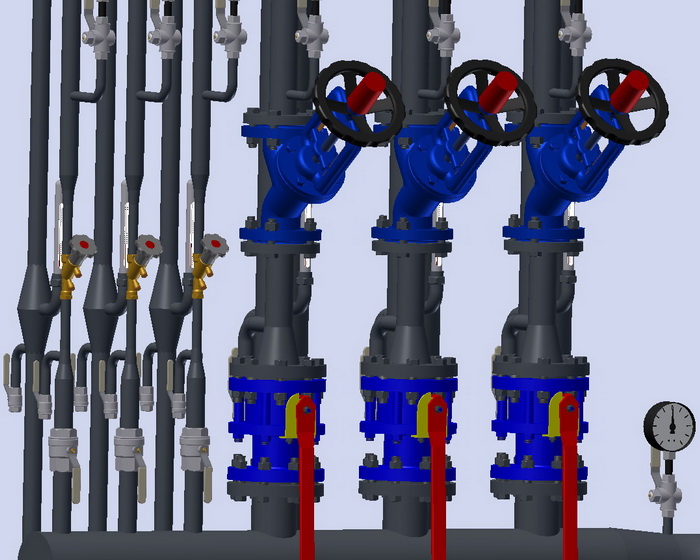
Die Installation des Abgleichventils erfolgt gemäß den Montageanweisungen. Darüber hinaus sollten die folgenden Empfehlungen beachtet werden:
- Vor dem Ventil sollte ein Siebfilter installiert werden.
- Es wird empfohlen, vor und nach dem Ventil Manometer zu installieren.
- Die Einbaulage kann beliebig sein, sofern sie den Installationsanweisungen nicht widerspricht.
- Der Pfeil am Ventilkörper muss mit der Fließrichtung des Wassers an der Einbaustelle übereinstimmen.
- Der Körper des Abgleichventils darf keine Biege-, Dreh-, Zug- oder Druckbelastungen aufnehmen.
- Der Einbauort des Abgleichventils muss für Wartung, Einstellung und Durchflussmessung zugänglich sein.
- Verschiedene Hersteller geben unterschiedliche Daten an, aber im Durchschnitt wird empfohlen, vor dem manuellen Abgleichventil 5DN und nach dem Ventil 10DN gerade Leitungsabschnitte einzuhalten.
Reihenfolge des Abdichtens von Schraubverbindungen
1. Nehmen Sie eine Hanffasersträhne mit so vielen Fäden, dass ihr Durchmesser im verdrehten Zustand ungefähr der Tiefe des Gewindes entspricht. Die Länge der Strähne sollte eine Anzahl von Wicklungen von 1,5 bis 2 Mal der Anzahl der Gewindegänge ermöglichen.
2. Drehen Sie die Strähne etwa 50-70 mm vom Anfang entfernt leicht zusammen und legen Sie sie in den ersten Gewindegang. Halten Sie sie mit der Hand fest und wickeln Sie das lange Ende der Strähne im Uhrzeigersinn fest um, wobei sie in jeden Gewindegang eingelegt wird.
3. Wickeln Sie bis zum Ende des Gewindes und setzen Sie die Wicklung mit einer zweiten Schicht fort, indem Sie die Windungen zum Anfang des Gewindes verschieben. Die Länge der zweiten Wickelschicht sollte ungefähr 2/3 der Länge des Gewindes betragen.
4. Das verbleibende Ende der Strähne (50-70 mm) wird ebenfalls im Uhrzeigersinn aufgewickelt, von Ende bis Anfang des Gewindes.
5. Tragen Sie eine Schicht Dichtmittel auf die Oberfläche der Wicklung auf.
6. Schrauben Sie die Verbindungselemente von Hand zusammen. Bei richtiger Wicklung sollte sich das montierte Element 1,5 bis 2 Umdrehungen drehen.
7. Verwenden Sie einen Schraubenschlüssel oder Drehmomentschlüssel, um das Element weiter anzuziehen. Falls das montierte Element in einer bestimmten Position sein muss, beenden Sie das Festziehen in der gewünschten Position.
Bei korrekter Abdichtung sollte während des Anziehens das Drehmoment die unten angegebenen Werte nicht überschreiten:
| DN15 | DN20 | DN25 | DN32 | DN40 | DN50 | DN65 | DN80 | DN100 |
|---|---|---|---|---|---|---|---|---|
| 70 Nm | 95 Nm | 120 Nm | 150 Nm | 190 Nm | 230 Nm | 280 Nm | 350 Nm | 400 Nm |
Schraubmomente für Flanschverbindungen
| DN | Schraube/Muttern | Drehmoment, Nm |
|---|---|---|
| 15 - 32 | M 10 | 15 - 30 |
| 40 - 65 | M 12 | 35 - 50 |
| 80 - 100 | M 16 | 75 - 100 |
| 125 - 150 | M 16 | 80 - 120 |
| 200 | M 20 | 150 - 200 |
| 250 - 400 | M 24 | 340 - 410 |
| 500 | M 27 | 340 - 410 |


 Tutorial Danfoss
Frage : Kommentar : Rückmeldung
341
 Katalog von
 Wärmezähler
Herz
Herz
Herz
Herz
Herz
Herz
Herz
Herz
Zetkama
Zetkama
Danfoss
Danfoss
Danfoss
Danfoss
Danfoss
Honeywell - Resideo
Honeywell - Resideo
Honeywell - Resideo
Honeywell - Resideo
Oventrop
Oventrop
Oventrop
IMI Hydronic
IMI Hydronic
IMI Hydronic
IMI Hydronic
IMI Hydronic
IMI Hydronic
ARI Armaturen
ARI Armaturen
Vexve
Vexve
VIR
VIR
VIR
Danfoss
Danfoss
IMI Hydronic
IMI Hydronic
IMI Hydronic
IMI Hydronic
Zetkama
Zetkama
VIR
Comap
Comap
Comap
Herz
Vexve
Vexve
Broen
Broen
Broen
Broen
Broen
Broen

