Bitte blockieren Sie keine Werbung auf unserer Website. Klicks auf Anzeigen helfen uns, zu existieren, zu wachsen und für Sie nützlicher zu werden!
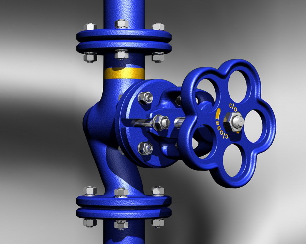
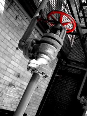
Montage des Absperrventils
Empfehlungen für die Montage
Die Ventile können in jeder Einbaulage an vertikalen oder horizontalen Rohrleitungen installiert werden, außer mit dem Stiel nach unten.
Das Ventil ist einseitig ausgerichtet, daher muss die Flussrichtung des Mediums mit dem Pfeil auf dem Gehäuse übereinstimmen. Das Arbeitsmedium wird unter den Schieber geleitet. Die Verwendung des Ventils im Rückwärtsmodus ist nicht zulässig, da dies bei längerem Gebrauch zum Bruch des Schiebers führen kann.
Absperrventile mit elektrischen Antrieben müssen mit dem Stiel nach oben installiert werden, es sei denn, in der Montageanleitung ist eine andere Einbaulage vorgesehen. Wenn sie im Freien installiert werden, sollte über dem elektrischen Antrieb ein Schutzdach angebracht werden.
Schutz des Gehäuses vor Biegespannungen
Das Ventilgehäuse darf keine Biege-, Dreh-, Zug- oder Druckspannungen von den angeschlossenen Rohrleitungen erfahren, insbesondere bei Ventilen mit Gusseisengehäuse.
Die entsprechenden Flansche müssen parallel sein, und es ist nicht zulässig, den Flanschwinkel durch zusätzliche Dichtungen und Anziehen der Befestigungsschrauben auszugleichen.
Bei der Installation von Ventilen an langen, geraden Rohrleitungsabschnitten, die Temperaturänderungen des Arbeitsmediums oder der Umgebungsluft ausgesetzt sind, sollte das Ventil auf einem festen Stützpunkt oder einem axialen Kompensator mit Führungen installiert werden, um ein Verschieben der Rohrleitung relativ zu ihrer Achse zu verhindern.
Montagehinweise
Vor der Installation sollte die Funktionsfähigkeit des Schiebers überprüft werden, indem dieser 2-3 Mal geöffnet und geschlossen wird.
Bei einem Nenndurchmesser DN > 100 mm sollten unter dem Ventil und der angeschlossenen Rohrleitung Stützen angebracht werden.
Zum Transport und zur Installation von Großventilen an der Einbaustelle sollten die werkseitigen Hebeösen verwendet werden. Es ist nicht zulässig, das Ventil am Handrad, Getriebe oder elektrischen Antrieb aufzuhängen.
Nach Abschluss der Montage im Rohrleitungsabschnitt sollten hydraulische Druckprüfungen auf Festigkeit und Dichtheit durchgeführt werden. Während der hydraulischen Prüfungen muss der Schieber des Ventils entweder vollständig geöffnet oder vollständig geschlossen sein. Hydraulische Prüfungen mit dem Schieber in Zwischenstellung sind nicht zulässig.
Das Material der Zwischenflanschdichtungen wird entsprechend der maximalen Betriebstemperatur und dem Druck an der Einbaustelle des Ventils ausgewählt.
- Paronit-Dichtung wird bei einem Betriebsdruck bis 63 bar und Temperaturen von -50 bis 450°C verwendet.
- PTFE-Dichtung wird bei einem Betriebsdruck bis 70 bar und Temperaturen von -120 bis +150°C verwendet.
- EPDM-Gummidichtung wird bei einem Betriebsdruck bis 16 bar und Temperaturen von 0 bis 60°C verwendet.
Anzugsmomente der Flanschverbindungsmuttern
| DN | Mutter/Schraube | Drehmoment, Nm |
|---|---|---|
| 15 - 32 | M 10 | 15 - 30 |
| 40 - 65 | M 12 | 35 - 50 |
| 80 - 100 | M 16 | 75 - 100 |
| 125 - 150 | M 16 | 80 - 120 |
| 200 | M 20 | 150 - 200 |
| 250 - 400 | M 24 | 340 - 410 |
| 500 | M 27 | 340 - 410 |


 EN 1092-1
Frage : Kommentar : Rückmeldung
279
 Katalog von
