Bitte blockieren Sie keine Werbung auf unserer Website. Klicks auf Anzeigen helfen uns, zu existieren, zu wachsen und für Sie nützlicher zu werden!
Installation der Umwälzpumpe
Installation der Umwälzpumpe in Heizungs- und Warmwassersystemen muss gemäß dem Entwurf dieser Systeme und den Anweisungen des Herstellers zur Installation erfolgen. Nachfolgend finden Sie allgemeine Empfehlungen zur Installation von Pumpen mit Nassläufer:
Montageposition
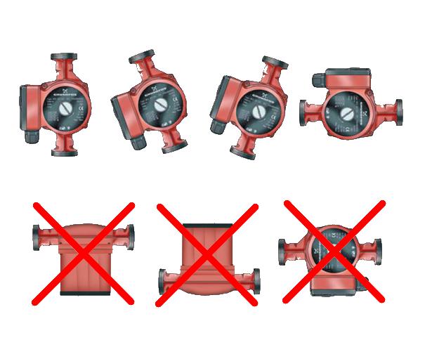
- Die Welle muss horizontal positioniert sein. Andernfalls wird die Pumpe überhitzen und durch den Schutz abgeschaltet.
- Nassläuferpumpen benötigen keine Stützrahmen oder Fundamente, es sei denn, die Montageanleitung sieht etwas anderes vor.
- Der Pfeil auf dem Pumpengehäuse muss mit der Flussrichtung des Wassers am Installationsort übereinstimmen.
- Die Umwälzpumpe kann sowohl in der Vorlauf- als auch in der Rücklaufleitung des Heizungssystems installiert werden, obwohl aus betrieblichen Gründen empfohlen wird, die Umwälzpumpe an einer Stelle mit der niedrigsten Temperatur des zu pumpenden Wassers zu installieren.
- Die Wärmedämmung erfolgt nur am Pumpengehäuse. Es ist nicht zulässig, den Motor zu isolieren.
Rohrleitungsverbindung
- Der Durchmesser der Zu- und Ableitungen sowie die Nennweiten der darauf montierten Armaturen werden berechnet und übersteigen in der Regel die Nennweite der Pumpenflansche um 1-2 Größen. Daher erfolgt der Anschluss der Leitungen an die Pumpe über Übergangsstücke.
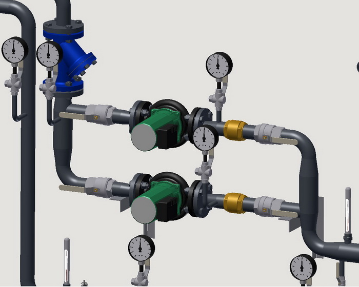
- Vor der Umwälzpumpe, in Strömungsrichtung des Wassers, sollte ein Siebfilter installiert werden, und vor und nach der Pumpe Absperrventile, Antivibrationsfugen und Manometer. Kleinleistungs-Pumpen können ohne Antivibrationsfugen installiert werden.
- Wenn zwei oder mehr Pumpen parallel installiert werden, sollte am Druckflansch jeder Pumpe ein Rückschlagventil installiert werden. In Heizsystemen ist die Installation einer Reserve-Umwälzpumpe obligatorisch.
- Das Pumpengehäuse darf keinen Torsions-, Zug-, Biege- oder Druckkräften durch die angeschlossenen Rohrleitungen ausgesetzt werden. Die Anschlussleitungen müssen fluchtend sein.
- Bei Gewindeanschlüssen sollte die Pumpe mit Überwurfmuttern (Amerikaner) installiert werden.
- Bei Flanschmontage müssen die Flansche parallel sein, und zwischen den Flanschen sollten Dichtungen aus einem für das Arbeitsmedium geeigneten Material installiert werden, wobei unter die Zugschrauben und Muttern Unterlegscheiben gelegt werden.
- Wenn sich Luft im Pumpenkreislauf ansammeln kann, sollten automatische Entlüfter an den möglichen Ansammlungsstellen installiert werden.
- An der tiefsten Stelle der abgeschalteten Rohrleitung mit der Pumpe sollte ein Entwässerungshahn installiert werden.
- Vor der Installation der Umwälzpumpe sollten die zugeführten Rohrleitungseinheiten gespült werden.
Elektrischer Anschluss
- Der Anschluss der Pumpe an das Stromnetz muss über ein Steuerpult mit einer Grundliste an Schutz- und Steuerfunktionen erfolgen.
- Die Einbauposition der Pumpe muss das Eindringen von Wasser in die Anschlussdose verhindern. Es wird nicht empfohlen, die Anschlussdose unterhalb des Motors zu installieren.
- Pumpen, die gegen Blockierströme beständig sind, und Pumpen mit integriertem Überhitzungsschutz der Wicklungen benötigen keinen zusätzlichen Schutz.
- Das Pumpengehäuse muss geerdet sein.
Vorgang zum Abdichten einer Gewindeverbindung
1. Nehmen Sie ein Bündel Flachsfasern, wobei die Anzahl der Fasern so gewählt werden sollte, dass der Durchmesser des verdrehten Bündels etwa der Tiefe des Gewindes des zu montierenden Elements entspricht. Die Länge des Bündels sollte 1,5-2 Mal mehr Wicklungen ermöglichen als die Anzahl der Gewindegänge.
2. Verdrehen Sie das Bündel etwa 50-70 mm vom Anfang entfernt leicht, legen Sie es in die erste Gewindewindung und wickeln Sie den langen Strang im Uhrzeigersinn fest um das Gewinde, sodass es in jede Gewindewindung passt.
3. Wickeln Sie weiter bis zum Ende des Gewindes und fahren Sie mit einer zweiten Schicht fort, indem Sie die Windungen zurück zum Anfang des Gewindes verschieben. Die Länge der zweiten Wickelschicht sollte etwa 2/3 der Gewindelänge betragen.
4. Wickeln Sie das verbliebene Ende des Bündels (50-70 mm) ähnlich im Uhrzeigersinn, sodass es vom Ende des Gewindes zurück zum Anfang passt.
5. Tragen Sie eine Schicht Dichtmittel auf die Oberfläche der Wicklung auf.
6. Schrauben Sie die Verbindungsteile mit der Hand zusammen. Bei korrekter Wicklung sollten sich die Elemente 1,5-2 Umdrehungen einschrauben lassen.
7. Fahren Sie mit einem Schraubenschlüssel oder Drehmomentschlüssel fort. Wenn das montierte Teil in einer bestimmten Position fixiert werden muss, schließen Sie das Verschrauben in der gewünschten Position ab.
Bei korrekter Wicklung sollten die Anzugskräfte beim Einschrauben das unten angegebene Drehmoment nicht überschreiten:
| DN15 |
DN20 |
DN25 |
DN32 |
DN40 |
DN50 |
DN65 |
DN80 |
DN100 |
| 70 Nm |
95 Nm |
120 Nm |
150 Nm |
190 Nm |
230 Nm |
280 Nm |
350 Nm |
400 Nm |
Anzugsdrehmomente der Sechskantmuttern bei Flanschverbindungen
| DN |
Mutter/Schraube |
Drehmoment, Nm |
| 15 - 32 |
M 10 |
15 - 30 |
| 40 - 65 |
M 12 |
35 - 50 |
| 80 - 100 |
M 16 |
75 - 100 |
| 125 - 150 |
M 16 |
80 - 120 |
| 200 |
M 20 |
150 - 200 |
| 250 - 400 |
M 24 |
340 - 410 |
| 500 |
M 27 |
340 - 410 |


 Heating and domestic hot water systems for dwellings
Frage : Kommentar : Rückmeldung
1174
 Katalog von
 Umwälzpumpen
DAB
DAB
DAB
DAB
Wilo
Wilo
Wilo
Wilo
IMP Pumps
IMP Pumps
IMP Pumps
IMP Pumps
IMP Pumps
Calpeda
Calpeda
Calpeda
Calpeda
Calpeda
Grundfos
Wilo
Wilo
Wilo
Wilo
Wilo
Calpeda
Calpeda
Grundfos
Grundfos
Grundfos
Grundfos
Grundfos
DAB
DAB
Smedegaard
Smedegaard
Smedegaard
Lowara
Lowara
Lowara
Lowara
Lowara
IMP Pumps

