Please do not block ads on our site. Clicks on ads help us exist, grow and become more useful for you!
Calculation and Selection of Self-acting Water Temperature Regulator
 EXAMPLE


Temperature Regulator Selection
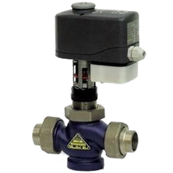
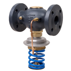
A self-acting temperature regulator is an independent element of the heat supply system that does not require additional components and operates without external energy sources.
The main task of the temperature regulator is to control the heating or cooling process of the working medium by blocking the flow of heat or cold carrier. The regulating ability is determined by the valve's authority in the controlled system, therefore it is recommended to choose a valve taking into account the curvature of its regulating characteristic, associated with the deviation of the temperature regulator's authority from 1. Otherwise, the regulation process may occur in a two-position mode.
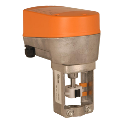
The accuracy of maintaining the temperature by the regulator depends on the hysteresis and proportionality zone of the thermal actuator, and the reaction speed to temperature deviations depends on the time constant.
In systems with rapidly changing parameters, it is better to prefer 'fast' regulators with a time constant of up to 60 seconds, and in systems with storage water heaters and heat accumulators, 'slower' regulators will suffice.
It is recommended to choose the temperature regulator's thermal actuator so that the maintained temperature is in the middle third of the regulated range.
Calculation Methodology
The calculation and selection methodology for a temperature regulator involves determining:
- the required flow capacity of the regulator
- the optimal range of supported temperatures
- the closing speed and maintenance accuracy
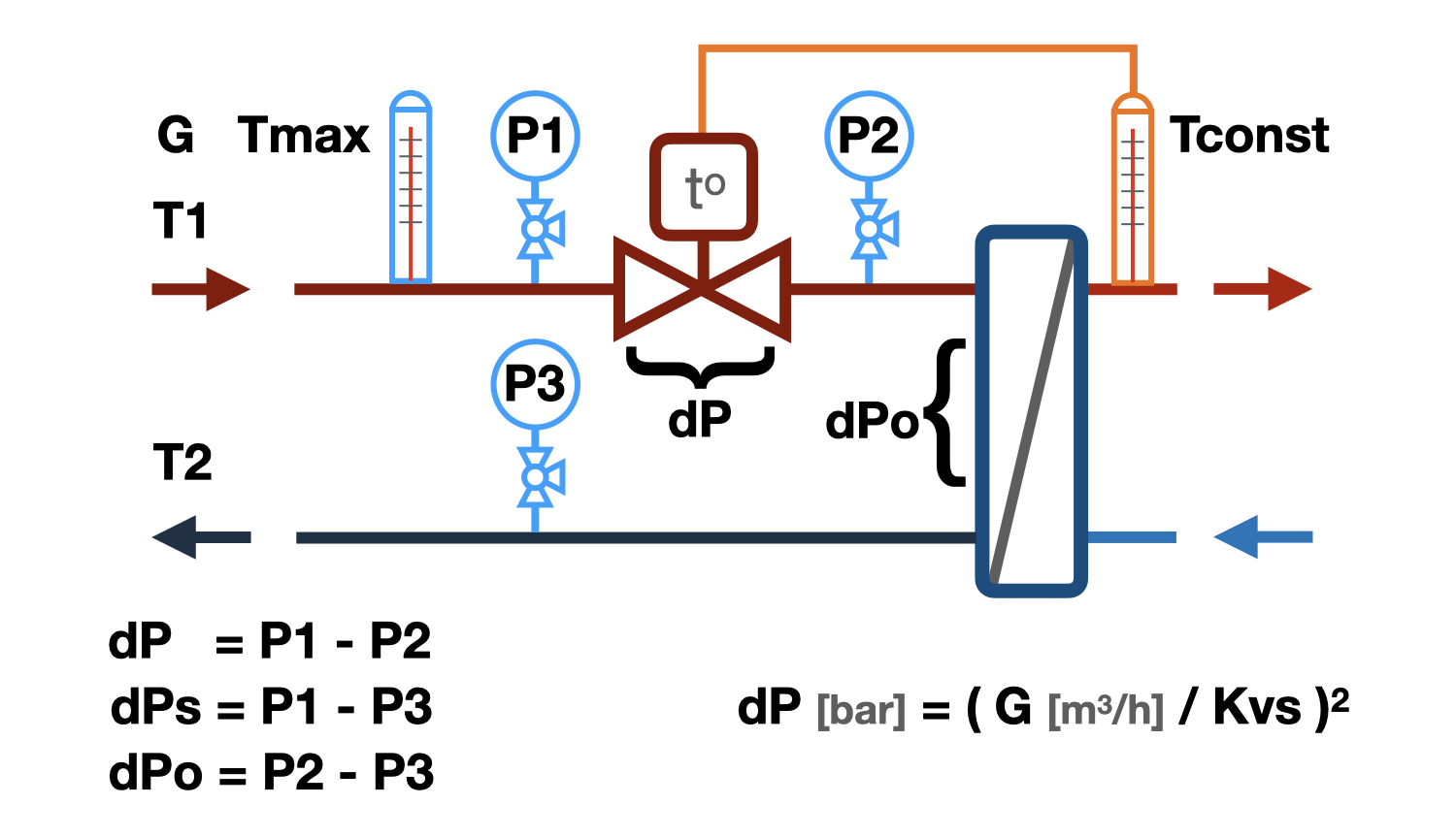
Flow Capacity Calculation
The flow capacity calculation of the Kv temperature regulator is based on data about the heat carrier flow through it and the permissible head loss. It should be noted that the greater the percentage of losses in the controlled section contributed by the temperature regulator from the available excess pressure, the higher its authority, and the regulation will be smoother.
The algorithm for selecting a temperature regulator described above, when calculating the deviation of the valve's regulating characteristic from the authority of 1, by default uses the initial operating characteristic - linear.
Calculation of the Possibility of Cavitation Occurrence
Cavitation is the formation of vapor bubbles in the water flow, which manifests when the pressure in it drops below the saturation pressure of water vapor. Bernoulli's equation describes the effect of increasing flow velocity and decreasing pressure in it, which occurs when the flow area narrows. The flow area of the temperature regulator is exactly such a narrowing, the pressure in which can drop to the saturation pressure, and the place of the most likely cavitation formation. Vapor bubbles are unstable, they appear sharply and disappear just as sharply, this leads to the erosion of metal particles from the valve gate, which will inevitably cause its premature wear. In addition to wear, cavitation leads to increased noise during valve operation.
The main factors affecting the occurrence of cavitation:
- Water temperature - the higher it is, the greater the likelihood of cavitation.
- Water pressure - before the regulating valve, the higher it is, the lower the likelihood of cavitation.
- Permissible pressure drop - the higher it is, the higher the likelihood of cavitation. It should be noted here that in the valve gate position close to closing, the throttled pressure at the temperature regulator tends to the excess pressure in the controlled section.
- Cavitation characteristic of the temperature regulator - determined by the features of the valve's regulating element. The cavitation coefficient is different for different types of regulators and should be indicated in their technical characteristics. However, since most manufacturers do not specify this value, the calculation algorithm includes the range of the most likely cavitation coefficients.
Temperature Regulator Noise Calculation
High flow velocity in the temperature regulator's inlet pipe can cause a high noise level. For most rooms where temperature regulators are installed, the permissible noise level is 35-40 dB (A), which corresponds to a velocity in the valve's inlet pipe of approximately 3 m/s. Therefore, when choosing a temperature regulator, it is recommended not to exceed the specified velocity.
question : comment : feedback
 Online Equipment calculations