Please do not block ads on our site. Clicks on ads help us exist, grow and become more useful for you!
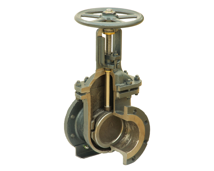
Construction of the gate valve
The main difference between a gate valve and other types of valves is that the flat closure is attached to a threaded stem and moves in a plane perpendicular to the flow axis.
Gate Valve Structure
- Valve element (wedge, gate, parallel single-disc or double-disc)
- Body (cast iron, steel, or brass)
- Cover (cast iron, steel, or brass)
- Threaded stem (spindle), usually made of steel
- Handwheel, gear drive, or electric actuator
Classification by Closure Structure
Wedge gate valves are usually made in a full-bore design with a non-rising stem, a rigid, flexible or spring-loaded wedge, which allows the wedge angle to deform. The tightness of the flow closure is ensured by sealing metal/metal or rubber/metal for valves with a rubber wedge. Gate valves are available with threaded or flanged connections to the pipeline.
Wedge gate valves are widely used in technological and trunk pipelines, in systems with high temperature and pressure of the working medium. Wedge gate valves are widely used in municipal water supply systems.
Parallel gate valves (double-disc) are made with a flanged body made of cast iron or steel with a rising or non-rising stem. The tightness of the flow closure is achieved by sealing metal/metal between the closure element and the body.
Parallel gate valves are used for low water pressure, usually not exceeding 10 bar. For a long time, the parallel gate valve 30ch6br was used as the main shut-off valve in engineering systems, but with the appearance of ball valves and disc closures, it lost its position.
Knife gate valve has proven itself to be very effective in systems with loose, dense, and viscous working media, and is widely used in drainage, chemical, and food industries. Knife gate valves are produced in a between-flange design, which makes them low in weight and, as a result, relatively inexpensive.The construction of these valves requires a full-bore execution with a glandless seal of the stem. Thanks to their design, knife gate valves provide a very reliable hermetic flow shut-off, but are only operated at low pressures. The body of the knife gate valve can be made of cast iron, steel, or stainless steel, and the sealing and knife seat depend on the working parameters and are made of various polymer materials.
By body material
Valves are made of cast iron, steel, brass, and bronze. Valves made of brass and bronze are produced in a threaded design with a nominal diameter of up to 50 mm and are very rarely used. Steel and cast iron valves are produced in flanged and between-flange designs and are more widely used.
Cast iron gate valves are suitable for solving most general-purpose tasks and are used in areas with pressures below 10 bar. Cast iron is a brittle metal, so cast iron valves need to be protected from torsional, tensile, compressive, and bending forces from connected pipelines.
Recently, cast iron valves are less commonly used in heating and water supply systems, but have not lost their position in steam systems, as well as when used on pipelines with viscous media and sewage.
Steel gate valves are installed on pipelines with high working medium parameters and high reliability requirements, and are widely used in high-temperature heat sources and external heat supply networks.
By type of control
Handwheels are used for manual control of valves with a diameter up to DN150, while gearbox drives are used for larger valves.
Valves with an electric actuator are used in cases of process automation, remote control, for large diameter valves (DN500 and above), or when located in hard-to-reach places.
To open the valve, the electric actuator must make a large number of turns. This allows the use of low-power electric actuators, but excludes the possibility of quick opening or closing. This feature makes it impossible to use valves with electric actuators for quick flow shutdown, but gives them a huge advantage in systems that do not allow hydraulic shocks. In order to reduce the load on the electric actuator and prevent hydraulic shocks, relief bypass lines of smaller diameter are added to larger valves.
By opening mechanism
Valves with extending and non-extending stems (spindles) are distinguished. Valves with extending stems are less expensive and have a larger overall height compared to valves with non-extending stems.
question : comment : feedback
272
 Catalog of
 gate valves
ГОСТ
ГОСТ
Genebre
Genebre
IVR
CMO
CMO
CMO
CMO
Hawle
Hawle
Hawle
Ukspar
Ukspar
Brandoni
Brandoni
AEON
FAF
AVK
AVK
AVK
Herz
Polix
Polix
Polix
IMI Hydronic
IMI Hydronic
Oventrop
Oventrop
FAF
Zenit
EBRO Armaturen
AVK
AVK
AVK
AVK


 EN 1092-1
