Please do not block ads on our site. Clicks on ads help us exist, grow and become more useful for you!
Connection diagram of the pressure tank
The connection diagram of the pressure tank depends on its assigned function. Below are the most common installation diagrams for pressure tanks in water supply systems.
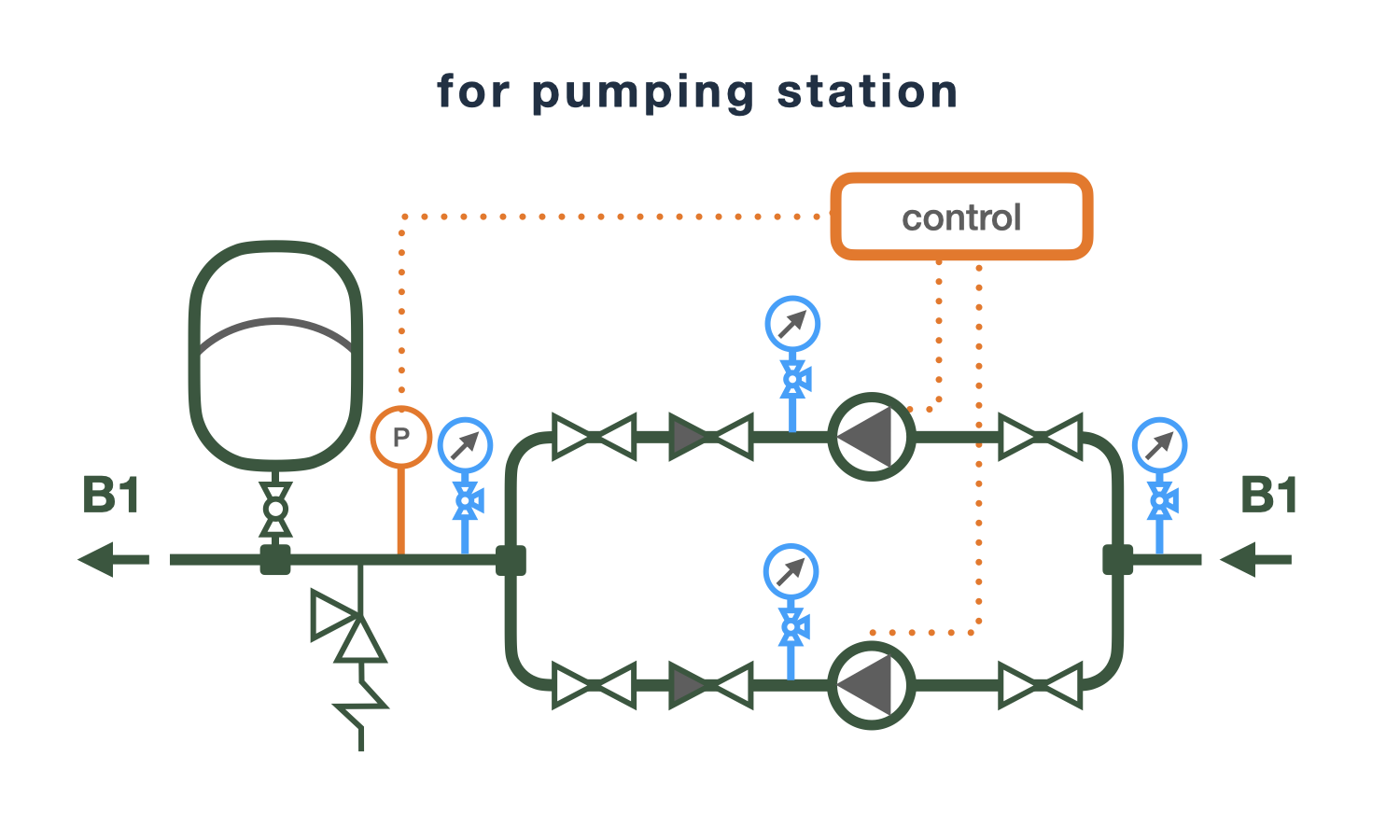
In the circuit of the booster pump station
Booster pump stations are installed at facilities with significant water consumption, and typically one of the pumps operates continuously. The pressure tank for the booster pump station is used to smooth out pressure spikes when additional pumps are activated and to compensate for minor water withdrawals.
Additionally, this connection scheme for the pressure tank is used in water supply systems with frequent power interruptions, where the absence of water during power outages is not allowed. In this case, the stored volume of water in the pressure tank acts as a reserve used during power outages. If the pressure tank is installed as a buffer tank, its volume will need to be larger as the water reserve increases and the difference between the cut-in and cut-off pressures of the pump decreases.
Pressure tank for submersible pumps
The optimal switching mode for submersible pumps that can guarantee long-term and uninterrupted operation is usually from 5 to 20 starts per hour, as indicated in the technical specifications of this pump. The pressure switch turns on the pump when the water pressure in the supply system drops to the minimum value and turns it off when the maximum value is reached. Water is an incompressible liquid, so even a slight water consumption or leakage, especially in small water supply systems, will lower the water pressure to a minimal level and cause the pump to turn on, with a signal to turn it off being sent a few seconds later since there is no water consumption and the leakage is immediately compensated by the pump.
This operating mode is not beneficial for submersible pumps and may lead to rapid failure. The stored water in the pressure tank compensates for minor leaks and small water withdrawals, reducing the frequency of pump activation. Furthermore, the pressure tank in the scheme with the pump allows for smoothing out the instantaneous increase in water pressure when the pump is turned on.
The volume of the pressure tank depends on the optimal frequency of pump activation, its power, hourly water consumption, and the height at which the tank is installed.
In the scheme with a storage water heater
The pressure tank in the connection scheme of a storage water heater serves the function of an expansion tank. When heated, water expands, and the larger the volume of water in the hot water supply system, the greater the volume increase. Water, as is known, is nearly incompressible, and even a slight volume increase in a closed circuit will lead to a rise in pressure and destruction of system elements.
The volume of the pressure tank will need to be larger as the water volume in the water supply system and storage water heater increases, the higher the temperature to which the water is heated, and the lower the maximum allowable pressure in the water supply system.
Installation of the pressure tank on the suction side of the booster pump
The connection scheme of the pressure tank before the booster pumps in the direction of water flow is used to smooth out sharp pressure drops in the external water supply network during pump activation.
The volume of the tank will need to be larger as the water leakage increases and the smaller the difference between the minimum and maximum pressure in the water supply before the booster pump.
question : comment : feedback
1286
 Catalog of
 of pressure tanks
Zilmet
Zilmet
Aquapress
Aquapress
Elbi
Elbi
Reflex
Reflex
Reflex
Varem
Varem
Imera
Imera
Imera
Imera
Imera
Grundfos
Flamco
Flamco
Flamco
Reflex
Elbi
Elbi
Pneumatex
Pneumatex
Pneumatex


 Tutorial Reflex
