Please do not block ads on our site. Clicks on ads help us exist, grow and become more useful for you!
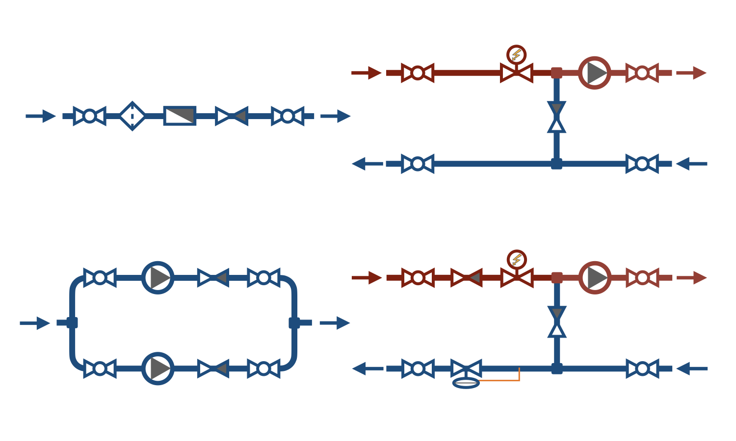
Check valve installation diagram
Check valves are installed in heating and water supply systems, in boiler rooms, and heat stations in places where, due to the technological process, unidirectional flow is permitted, and hydraulic pressure distribution in the system may cause reverse flow. Below are the most common check valve installation diagrams in building engineering systems.
1. In the pressure pipe of each pump in installations with two or more parallel pumps. The check valve prevents reverse water flow through the idle pump.
2. At the locations of water meters and heat meter flow sensors. In this scheme, the check valve is required for accurate flow measurement and protection of the flow meter.
3. In heat stations with dependent connections to centralized heating networks at the mixing nodes of the heat carrier. The check valve on the bypass prevents the flow of the heat carrier from the supply to the return pipe, bypassing the heating system.
4. In heat stations with dependent connections to centralized heating networks where the pressure in the supply pipe may drop below the static pressure of the heating system, a check valve is installed on the supply pipe, and a back-pressure regulator is installed on the return pipe. In this scheme, the check valve prevents the leakage of the heat carrier from the heating system when the pressure in the external heating network drops.
question : comment : feedback
564


 Tutorial Danfoss
 Catalog of
