Please do not block ads on our site. Clicks on ads help us exist, grow and become more useful for you!
Installation and mounting of a heat meter
Installation of heat meters used for commercial purposes can only be carried out by a licensed organization based on an approved project and in accordance with the attached installation instructions.
When installing a heat meter, attention should be paid to the following features:
- The room where the heat meter is located should be dry and prevent unauthorized access to the device.
- Power cables, the magnetic field of which may affect the operation of the meter, should not pass within 30 cm of the components of the heat meter and connecting wires.
- All components of the heat meter must be located in a place accessible for sealing, and the calculator and flow sensor - in a place accessible for reading the readings.
Installation of a flow sensor
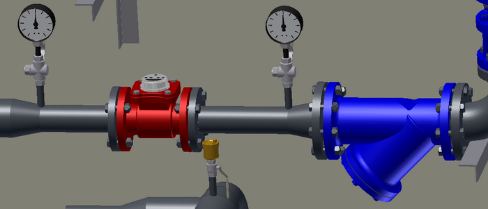
Straight sections of the pipeline should be left before and after the flow meter to calm the flow of the heat carrier (calming sections). The diameter of the calming section pipelines should correspond to the nominal diameter of the heat meter. The required length of the straight sections of the pipeline is given in multiples of the nominal diameter of the heat meter.
In heat meters with threaded connections, the calming sections are usually taken into account in the connecting fittings.
The installation location of the heat meter should prevent the formation of air plugs. If the heat meter is installed at the highest point of the pipeline, the section should be equipped with automatic air vents.
To protect against abrasive particles in the flow, a mesh filter should be installed in front of mechanical flow sensors.
Installation of temperature sensor
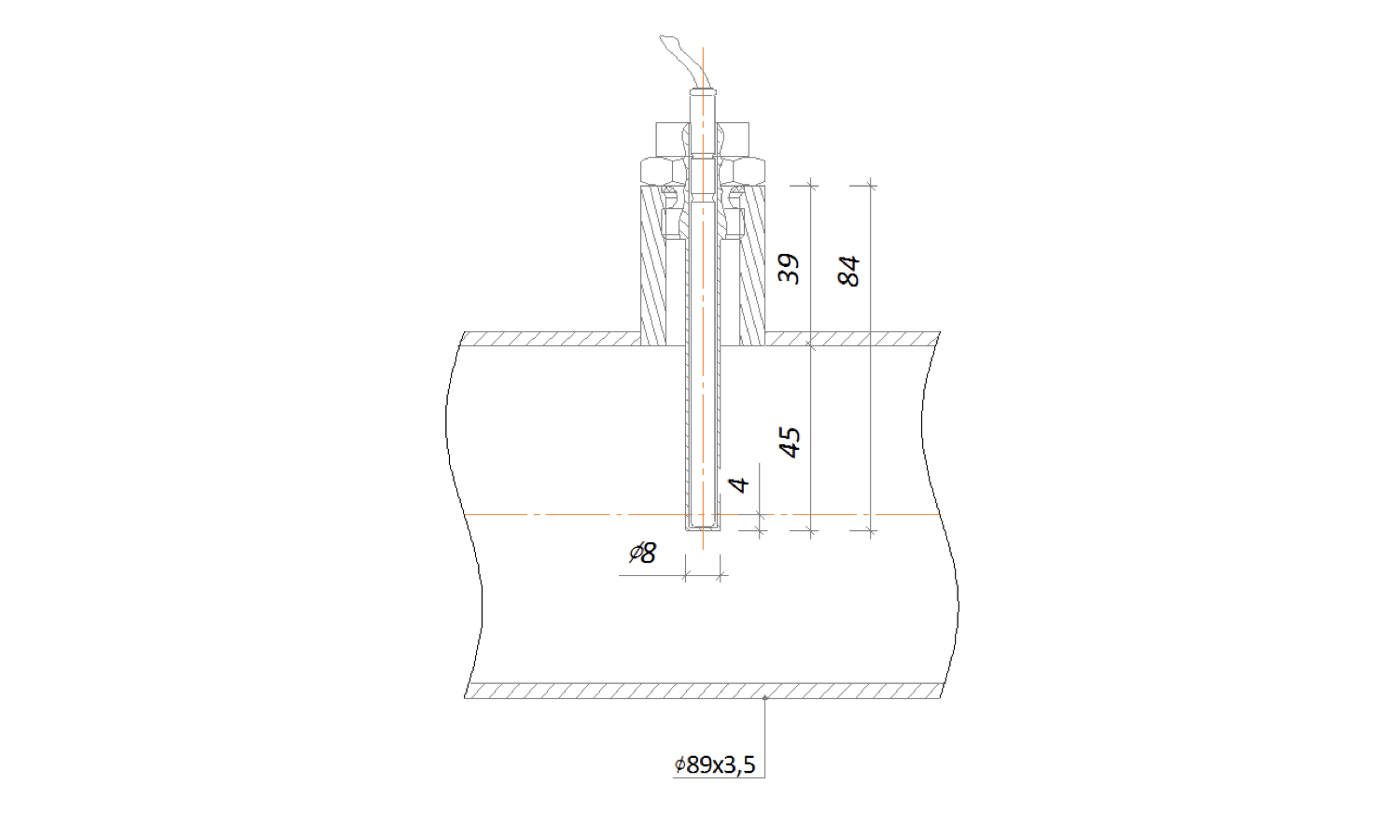
If the temperature sensor of the heat meter is immersed in the flow through a protective sleeve, the sleeve must be filled with machine oil before installing the sensor. The angle of inclination of the protective sleeve relative to the horizontal should prevent oil leakage.
The temperature sensor of the heat meter should be installed in such a way that the sensitive element of the sensor reaches the axis of the pipeline.
It is not allowed to install the temperature sensor of the heat meter near the point of mixing two streams of heat carrier. The distance from the mixing point to the installation location of the temperature sensor should be at least 10DN of the pipeline diameter.
Sequence for packing a threaded connection
1. Take a flax fiber string with enough threads so that its twisted diameter is approximately equal to the depth of the thread. The length of the string should provide for 1.5-2 times more windings than the number of thread turns.
2. Starting approximately 50-70 mm from the beginning of the string, slightly twist it, place it in the first thread turn, and, holding it with your hand, tightly wind a long branch of the string clockwise, placing it in each thread turn.
3. When reaching the end of the thread, continue winding with a second layer, shifting the turns to the beginning of the thread. The length of the second layer winding should be approximately equal to 2/3 of the thread length.
4. Wind the remaining end of the string (50-70 mm) similarly clockwise, from the end of the thread to its beginning.
5. Apply a layer of sealant to the winding surface.
6. Tighten the connecting elements by hand. With correct packing, the assembled element should turn 1.5-2 full rotations.
7. Continue tightening the element with a wrench or a torque wrench. In case the assembled element needs to be in a specific position, complete tightening it in the necessary position of the element.
With proper packing, during tightening, the force should not exceed the tightening torque listed below:
| DN15 | DN20 | DN25 | DN32 | DN40 | DN50 | DN65 | DN80 | DN100 |
|---|---|---|---|---|---|---|---|---|
| 70 Nm | 95 Nm | 120 Nm | 150 Nm | 190 Nm | 230 Nm | 280 Nm | 350 Nm | 400 Nm |
Tightening torques for flange connections
| DN | Nut/Bolt | Torque, Nm |
|---|---|---|
| 15 - 32 | М 10 | 15 - 30 |
| 40 - 65 | М 12 | 35 - 50 |
| 80 - 100 | М 16 | 75 - 100 |
| 125 - 150 | М 16 | 80 - 120 |
| 200 | М 20 | 150 - 200 |
| 250 - 400 | М 24 | 340 - 410 |
| 500 | М 27 | 340 - 410 |
question : comment : feedback
340
 Catalog of
 heat meters
Landis Gyr
Landis Gyr
DIEHL
Zenner
Zenner
Аква Украина
AXIOMA Metering
AXIOMA Metering
Kamstrup
Kamstrup
Itron
Семпал
Семпал
Sensus
Sensus
Engelmann
ИТ
Sontex
Maddalena
Danfoss
Danfoss
Danfoss
Kamstrup
Kamstrup
Kamstrup
Sontex
Sontex
Sontex
Sontex
DIEHL
DIEHL
Sensus
Sensus
Sensus
Sensus
Sensus


 EN 1092-1
