Per favore, non bloccare la pubblicità sul nostro sito. I clic sugli annunci ci aiutano a esistere, a crescere e a diventare più utili per te!
Come installare una valvola di ritegno
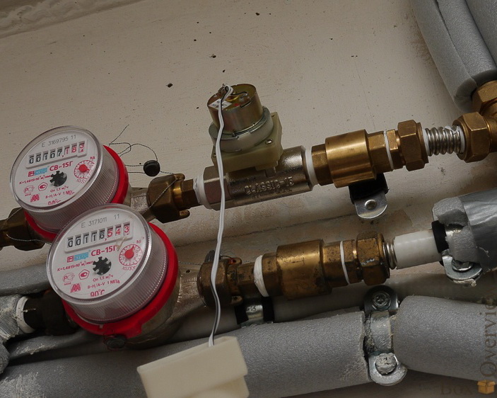
Le valvole di ritegno filettate si dividono in valvole con e senza molla. Le valvole con molla possono essere installate in qualsiasi posizione, mentre quelle senza molla vengono installate su tubazioni verticali con flusso dal basso verso l'alto o su tubazioni orizzontali.
Si consiglia di installare un filtro a rete prima della valvola di ritegno per proteggerla dalle sostanze abrasive presenti nel flusso.
Il corpo della valvola di ritegno non deve essere sottoposto a carichi di flessione, torsione, trazione o compressione provenienti dalla tubazione collegata.
La valvola di ritegno consente il flusso solo in una direzione, e la direzione del flusso è indicata da una freccia sul corpo della valvola: assicurarsi di installare correttamente la valvola in base allo schema tecnologico.
Non danneggiare il rivestimento di vernice sul corpo della valvola, poiché oltre alla funzione decorativa, esso protegge la valvola dalla corrosione.
Sequenza di imballaggio della giunzione filettata
1. Prendere un fascio di fibre di lino con un numero sufficiente di fili in modo che, in uno stato attorcigliato, il suo diametro sia approssimativamente uguale alla profondità del filetto. La lunghezza del fascio dovrebbe garantire 1,5-2 volte il numero di avvolgimenti rispetto ai giri del filetto.
2. Allontanarsi di circa 50-70 mm dall'inizio del fascio, attorcigliarlo leggermente, inserirlo nel primo giro di filetto e, tenendolo con la mano, avvolgere saldamente il ramo lungo del fascio in senso orario, inserendolo in ogni giro di filetto.
3. Raggiunta la fine del filetto, continuare l'avvolgimento con un secondo strato, spostando gli avvolgimenti verso l'inizio del filetto. La lunghezza del secondo strato dovrebbe essere di circa 2/3 della lunghezza del filetto.
4. Avvolgere l'estremità lasciata del fascio (50-70 mm) allo stesso modo in senso orario, dalla fine del filetto all'inizio.
5. Applicare uno strato di sigillante sulla superficie dell'imballaggio.
6. Stringere gli elementi di collegamento a mano. Con un corretto imballaggio, l'elemento montato dovrebbe stringersi di 1,5-2 giri.
7. Usare una chiave o una chiave dinamometrica per continuare a stringere l'elemento. Se è necessario posizionare l'elemento in una posizione specifica, completare il serraggio nella posizione desiderata.
Con un corretto imballaggio, durante il serraggio, lo sforzo non deve superare la coppia specificata di seguito:
| DN15 | DN20 | DN25 | DN32 | DN40 | DN50 | DN65 | DN80 | DN100 |
|---|---|---|---|---|---|---|---|---|
| 70 Nm | 95 Nm | 120 Nm | 150 Nm | 190 Nm | 230 Nm | 280 Nm | 350 Nm | 400 Nm |


domanda : commento : feedback
287
 Catalogo di
