Por favor, não bloqueie os anúncios em nosso site. Cliques nos anúncios nos ajudam a existir, crescer e se tornar mais úteis para você!
Instalação da válvula de balanceamento
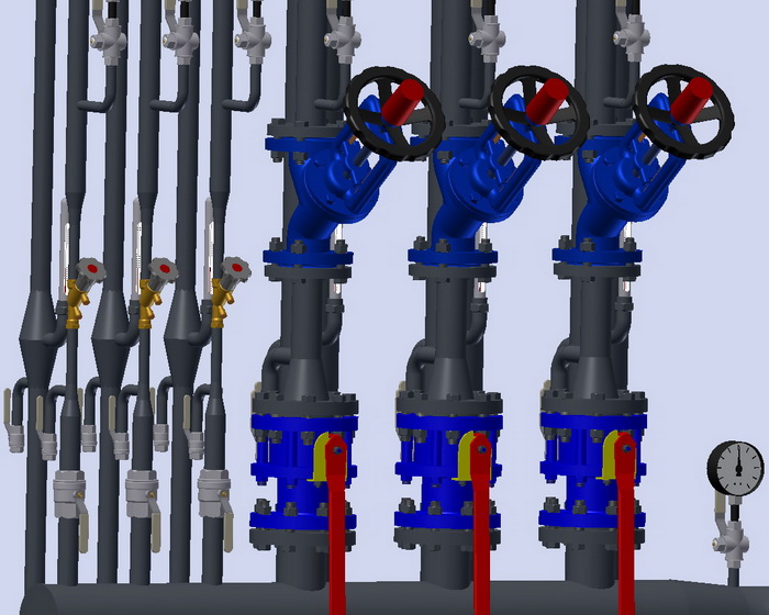
A instalação da válvula de balanceamento é realizada de acordo com o manual de instalação, além disso, as seguintes recomendações devem ser observadas:
- Deve-se instalar um filtro de malha antes da válvula.
- Recomenda-se a instalação de manômetros antes e depois da válvula.
- A posição de montagem pode ser qualquer, desde que não contrarie o manual de instalação.
- A seta no corpo da válvula deve coincidir com a direção do fluxo de água no ponto de instalação da válvula.
- O corpo da válvula de balanceamento não deve estar sujeito a cargas de flexão, torção, tração ou compressão.
- O local de instalação da válvula de balanceamento deve ser acessível para manutenção, ajuste e medição do fluxo.
- Diversos fabricantes fornecem dados diferentes, mas, em média, recomenda-se seguir trechos retos de 5DN antes e 10DN após a válvula de balanceamento manual.
Sequência de selagem de conexões roscadas
1. Pegue uma mecha de fibra de linho com um número suficiente de fios, de forma que, quando torcida, seu diâmetro seja aproximadamente igual à profundidade da rosca. O comprimento da mecha deve permitir um número de voltas de 1,5 a 2 vezes o número de voltas da rosca.
2. A cerca de 50-70 mm do início da mecha, torça-a ligeiramente e coloque-a no primeiro fio da rosca. Mantendo-a com a mão, enrole firmemente a mecha longa no sentido horário, colocando-a em cada volta da rosca.
3. Ao chegar ao fim da rosca, continue o enrolamento com uma segunda camada, movendo as voltas para o início da rosca. O comprimento da segunda camada de enrolamento deve ser de aproximadamente 2/3 do comprimento da rosca.
4. A extremidade restante da mecha (50-70 mm) deve ser enrolada da mesma forma no sentido horário, indo do final da rosca até o início.
5. Aplique uma camada de selante sobre a superfície do enrolamento.
6. Aperte manualmente os elementos de conexão. Com o enrolamento correto, o elemento montado deve apertar-se de 1,5 a 2 voltas.
7. Use uma chave de boca ou dinamométrica para continuar a apertar o elemento. Caso o elemento montado precise estar em uma posição específica, termine de apertá-lo na posição desejada.
Com o selamento correto, durante o aperto, a força não deve exceder os momentos de aperto indicados abaixo:
| DN15 | DN20 | DN25 | DN32 | DN40 | DN50 | DN65 | DN80 | DN100 |
|---|---|---|---|---|---|---|---|---|
| 70 Nm | 95 Nm | 120 Nm | 150 Nm | 190 Nm | 230 Nm | 280 Nm | 350 Nm | 400 Nm |
Momentos de aperto para conexões flangeadas
| DN | Parafuso/Porca | Momento de aperto, Nm |
|---|---|---|
| 15 - 32 | M 10 | 15 - 30 |
| 40 - 65 | M 12 | 35 - 50 |
| 80 - 100 | M 16 | 75 - 100 |
| 125 - 150 | M 16 | 80 - 120 |
| 200 | M 20 | 150 - 200 |
| 250 - 400 | M 24 | 340 - 410 |
| 500 | M 27 | 340 - 410 |


 Tutorial Danfoss
pergunta : comentário : opinião
569
 Catálogo de
 Contadores de Calor
Herz
Herz
Herz
Herz
Herz
Herz
Herz
Herz
Zetkama
Zetkama
Danfoss
Danfoss
Danfoss
Danfoss
Danfoss
Honeywell - Resideo
Honeywell - Resideo
Honeywell - Resideo
Honeywell - Resideo
ARI Armaturen
ARI Armaturen
Oventrop
Oventrop
Oventrop
IMI Hydronic
IMI Hydronic
IMI Hydronic
IMI Hydronic
IMI Hydronic
IMI Hydronic
VIR
VIR
VIR
Frese
Vexve
Vexve
Danfoss
Danfoss
IMI Hydronic
IMI Hydronic
IMI Hydronic
IMI Hydronic
Zetkama
Zetkama
VIR
Comap
Comap
Comap
Herz
Vexve
Vexve
Broen
Broen
Broen
Broen
Broen
Broen

