Por favor, não bloqueie os anúncios em nosso site. Cliques nos anúncios nos ajudam a existir, crescer e se tornar mais úteis para você!
Instalação da válvula globo
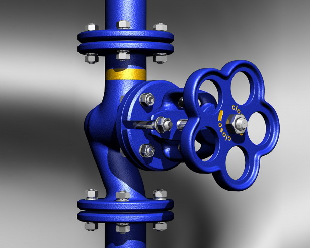
Recomendações de instalação
As válvulas podem ser instaladas em qualquer posição de montagem em tubulações verticais ou horizontais, exceto com a haste para baixo.
A válvula é unidirecional, portanto, a direção do fluxo do meio de trabalho deve coincidir com a seta no corpo. O meio de trabalho é fornecido sob o obturador. Não é permitido usar a válvula no modo reverso, pois o uso prolongado nesta configuração pode causar a ruptura do obturador.
As válvulas de bloqueio com atuadores elétricos devem ser instaladas com a haste para cima, a menos que outra posição seja especificada no manual de instalação. Se instalada ao ar livre, deve-se montar uma cobertura sobre o atuador elétrico.
Proteção do corpo contra tensões de flexão
O corpo da válvula não deve sofrer tensões de flexão, torção, tração ou compressão dos tubos conectados, especialmente no caso de válvulas com corpo de ferro fundido.
As flanges correspondentes devem estar paralelas, e não é permitido ajustar o ângulo da flange usando juntas adicionais ou apertando os parafusos de fixação.
Ao instalar válvulas em trechos longos e retos de tubulação que estão sujeitos a variações de temperatura do meio de trabalho ou do ar ambiente, a válvula deve ser montada sobre um suporte fixo ou um compensador axial com guias para evitar o deslocamento da tubulação em relação ao seu eixo.
Características de instalação
Antes da instalação, é necessário verificar o funcionamento do obturador, abrindo e fechando-o 2-3 vezes.
Para diâmetros nominais DN > 100 mm, devem ser usados suportes para a válvula e para o tubo conectado.
Para o transporte e instalação de válvulas de grande diâmetro no local de instalação, devem ser usados os olhais de içamento de fábrica. Não é permitido suspender a válvula pelo volante, redutor ou atuador elétrico.
Após concluir a instalação no trecho de tubulação, devem ser realizados testes hidráulicos de resistência e estanqueidade. Durante os testes hidráulicos, o obturador da válvula deve estar completamente aberto ou completamente fechado. Não é permitido realizar testes hidráulicos com o obturador em posição intermediária.
O material das juntas entre flanges é escolhido de acordo com a temperatura máxima de trabalho e a pressão no local de instalação da válvula.
- A junta de paronita é usada para pressões de trabalho de até 63 bar e temperaturas de -50 a 450°C.
- A junta de PTFE é usada para pressões de trabalho de até 70 bar e temperaturas de -120 a +150°C.
- A junta de borracha EPDM é usada para pressões de trabalho de até 16 bar e temperaturas de 0 a 60°C.
Momentos de aperto dos parafusos das conexões com flange
| DN | Porca/Parafuso | Momento, Nm |
|---|---|---|
| 15 - 32 | M 10 | 15 - 30 |
| 40 - 65 | M 12 | 35 - 50 |
| 80 - 100 | M 16 | 75 - 100 |
| 125 - 150 | M 16 | 80 - 120 |
| 200 | M 20 | 150 - 200 |
| 250 - 400 | M 24 | 340 - 410 |
| 500 | M 27 | 340 - 410 |


 EN 1092-1
pergunta : comentário : opinião
412
 Catálogo de
